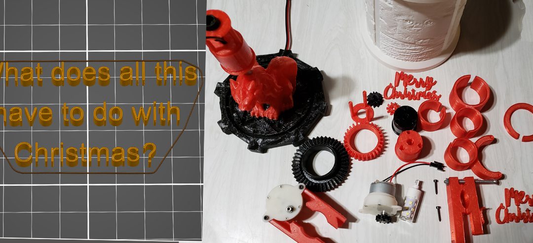
One of the attractions of a 3D printer is all the money you can save with 3D printed Christmas presents. I mean who wouldn’t want that collection of cute animal figures you’ve been printing. Never mind that it took sixty hours to print and that they could find better quality in the bargain bin of dollar general. It’s the thought that counts and you were thinking of them when you were printing. You were doing that, weren’t you?
Here was my plan in four easy steps:
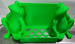
Possible present? Thingiverse: 3820895
Step one, pick the victim. I’ve used my printer to make present labels, ornaments and a few gifts. Still, I wanted this year to be different. Throughout the year my wife is frequently visited by hordes of Gnomes, rabbits, dragons and for Halloween, I made spiders. She’s very good natured about it but I sensed that 3D printed Christmas presents wouldn’t cut it. On the other hand, my mother in law is still enamored with the concept and made a perfect choice.
Step two, choose the design. I already knew what I wanted to do. There’s a wonderful website https://lithophanemaker.com. They will take your pictures and turn them into a lithopane. That’s a sort of picture that is illuminated from behind and gives a 3D effect. The site allows you to make flat lithopanes, round lithopanes and my favorite a four panel lamp shade. Perfect, all I had to do was talk my mother in law out of four pictures.
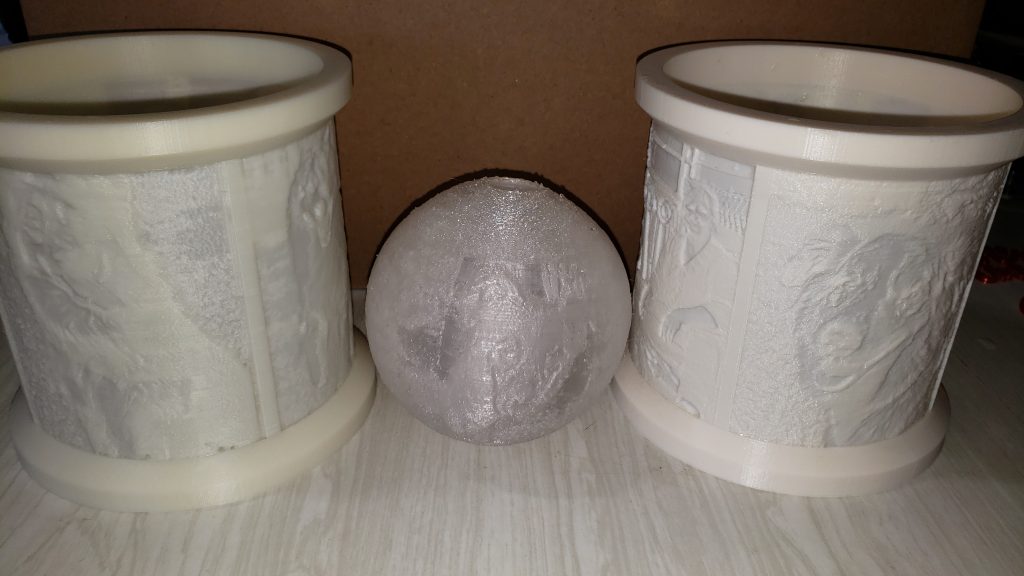
Lithopanes
Step three, print the design. 22 hours later I had her lamp shade printed. It looked great but needed a lamp to go with it. Maybe I could print a base for it. In fact, with a 3D printer, why limit myself to conventional?
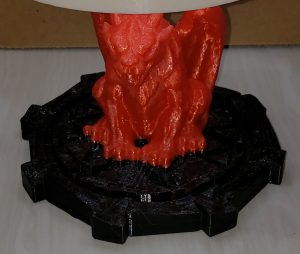 Those of you that decide to make one of your own, please let your imagination run wild. The gargoyle and base were selected because my mother in law loves gargoyles. I joined the two models together and put a hole through the gargoyle and base for the lamp support rod. As I write this, my mind is flooded with all the other choices I could have made but as it worked out, this was a good choice.
This was only a 16 hour print. I also wanted the base black and the gargoyle red so somewhere around 8 hours into the print I had to change filaments. Sorry, dear wife, now you know why my printer was beeping at 2am.
I still needed a way to support the lithopane on the lamp support rod. Realizing that someone would like a different view every once in a while, I created a support that the lamp shade could sit on and easily rotate.
Step four, try not to get distracted. I failed here. Those of you involved with engineers realize we can’t just make it simple. We tend to see the world as a series of improvement possibilities. Why make someone manually rotate the shade when it would be so simple to motorize the lithopane? In my own defense, I’m an electrical engineer not a mechanical engineer, but it seemed simple at the time.
Rotating the entire assembly was out because the wires would quickly twist up. Okay, I could have repurposed a wireless charger but I wanted it simple. All I really needed was a motor and some gears. Remember, electrical engineer.
Not to bore you with the details but my printer was fairly active for the next few days while I tested several design decisions. I had a working model when I started this post but in true engineering fashion, I wasn’t happy with the saddle clamp being used to mount the motor and decided to redesign it.
The real strength of a 3D printer is the ability to quickly prototype and refine concepts. I lost several days on this but my final design is simple to assemble and uses no screws. I’m sure there are better ways but I’m pleased with the final product.
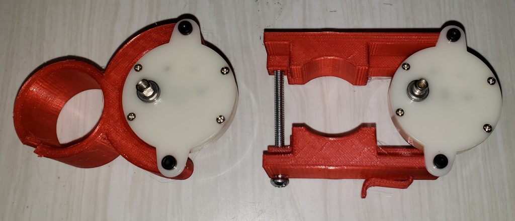
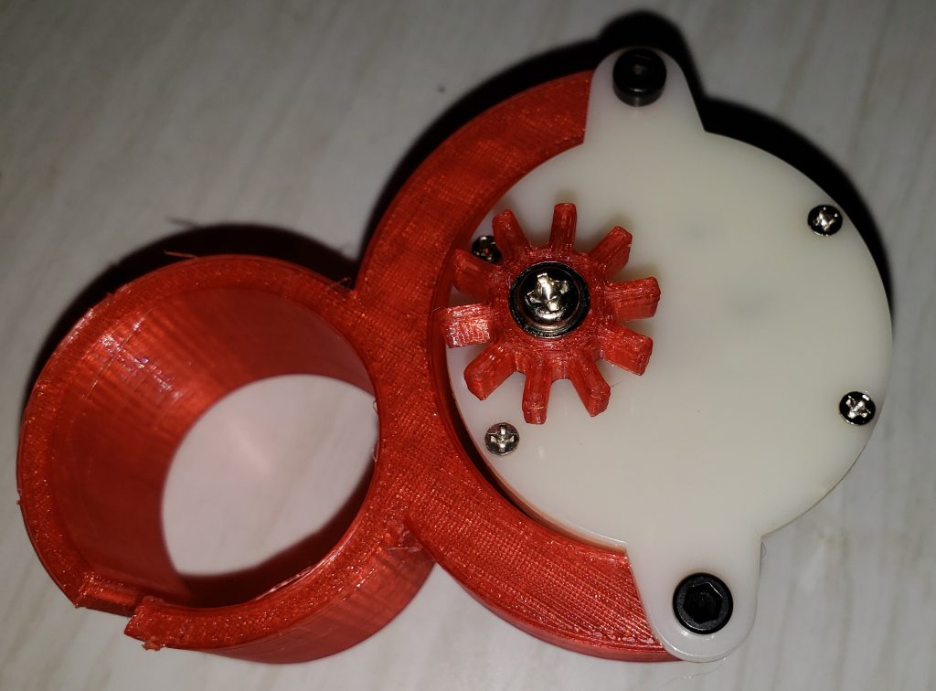
Simplified motor mount (left) versus my original motor mount (right)
Time to see how much money I saved.
- Lithopane – Free except for the plastic to print it. Let’s call it $3
- Motor – I ended up buying three different motors to get the speed I wanted. $16
- Lamp – Six lamps $18
- Lamp socket – Ten for $10
- 12v transformer with switch – I could have done this for 120V but decided 12V was safer. $18
- Plastic Filament – call it 1.5 rolls of filament after all the prototyping. $40
For a grand sum of slightly over $100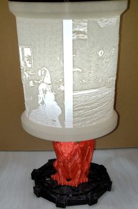
Hmm, more than I expected but now I have a finalized design and lots of spare parts. Future builds should cost less than $50 and I have lots of ideas. I will be putting all the part models on Thingiverse as well as creating detailed instructions with a bill of materials but for now consider how you would create your 3D printed Christmas presents.
PS: Those of you receiving this as an email will probably need to go to my site to see the video.
How to make your own
Before you start printing the pieces, here’s the parts list. Please be aware that this project requires soldering.
- https://smile.amazon.com/Precision-83063-Aluminum-Thickness-Diameter/dp/B00G6J7BDS K&S Precision Metals 83063 Round Aluminum Tube, 3/8″ OD x 0.049″ Wall Thickness x 12″ Length, 0.375 in OD. The size is important because there is a slight lip on the inside of the base and the lower lamp holder. Doing this allowed me to avoid glue. $7.00
- https://smile.amazon.com/gp/product/B07JNP475S Wal front DC 12V Gear Motor High Torque Slow Speed Micro Electric Motor Gearbox 3 RPM 4mm Shaft Diameter $8.29
- https://smile.amazon.com/gp/product/B07WLW1N7X Bayshe T10 Wedge Base LED Light Bulb 5 watt(6000K Daylight White) $19.99
- https://smile.amazon.com/gp/product/B078R93PSY 12V 2A 24W AC/DC Switching Power Supply Adapter with On/Off Switch $9.99
- https://smile.amazon.com/gp/product/B00W8W5MR4 uxcell 10 Pcs T10 Wedge Base Light Instrument Panel Dash Board Socket Plug $8.46
- https://smile.amazon.com/gp/product/B072BXB2Y8 DC Power Pigtail Cable Wire, 12V 5A Male & Female Connectors $9.89
- https://smile.amazon.com/gp/product/B06WGN56V2 eBoot 22 AWG JST SM 2 Pin Plug Male and Female Connector Adapter $7.29
You will also need an M3 screw for the motor shaft, two screws for attaching the motor (I used two #6 finishing screws) and some heatshrink tubing.
Depending on your collection of spare parts you may need to order very little of this. For example, I used the aluminum rod from one of my wife’s dead solar LED decorations, the power supply from a defunct security camera and both connectors from other projects. As you consider what you do have, note that changing the motor will require a redesign of the motor mount and changing the lamp base may force you to come up with another way to mount the lamp socket.
Select four of your favorite pictures and head over to https://lithophanemaker.com/Lamp Lithophane.html. His default lamp lithopane exceeds the size of my printer so I modified the settings as shown below. I wouldn’t suggest making it any smaller because the space between the motor and lithopane is less than 1/8 of an inch. I don’t recommend changing the dimensions in red because those define the inner mount for the lamp and my design requires those dimensions. Feel free to play with making the top and bottom diameters larger.
- Lithophane Resolution: 0.25
- Top Diameter: 150
- Bottom Diameter: 150
- Number of Half-Waves: 0
- Size of Waves: 0
- Height: 160
- Base Width and Height: 10
- Overhang Angle: 45
- Maximum Thickness: 3.0
- Minimum Thickness: 0.6
- Spacing Between Pictures: 10
- Frame Options: Clamp Interface
- Ledge Diameter: 27.6
- Ledge Height: 25
- Cylinder Diameter: 33.4
- Cylinder and Ledge Thickness: 2.5
- Spoke Thickness: 5
- Spoke Depth: 12.5
Print the lithopane and then go to https://www.thingiverse.com/thing:4049151 for the rest of the pieces. Your second print should be the lower lamp holder for a fit check.. Everything was printed in PETG, with 15% infill and .20 mm. Assuming the stars are properly aligned for you, lower lamp holder should easily slide into the inner mounting collar of the lithopane. This is a critical dimension and checking it now may spare you a lot of grief later. I mention this because I had several lithopanes printed on my other printer and the parts did not fit. Both parts had to be printed on the same printer. This is also a good time to test your aluminum tube. It should have a snug fit and not be able to pass through the fixture.
Not everyone likes gargoyles and changing this part of the design is easy. The only thing to consider is that the base diameter should be as large as the lithopane diameter. While you’re deciding on the base and figure, go ahead and print out the rest of the parts.
For the gargoyle, I used Gargoyle by Prodimensional, https://www.thingiverse.com/thing:458009 and Fantasy Wargame Terrain – Teleport/Summoning Circles by sablebadger, www.thingiverse.com/thing:3026114 as the base. I joined the two with Meshmixer and subtracted the material necessary to create the hole and wiring channel. This is included as negative material if you decide to make your own version. As a final touch, I had my slicer, PrusaSlicer, pause my printer at the gargoyle’s feet, allowing me to change filament and achieve the two-color appearance.
This is a good time to print the rest of the parts. As I said earlier, everything was printed in PETG, with 15% infill and .20 mm. You should have a large gear, a small gear, a motor mount, an upper lamp holder, the lower motor mount (already printed), the base, lithopane cover and the lithopane.
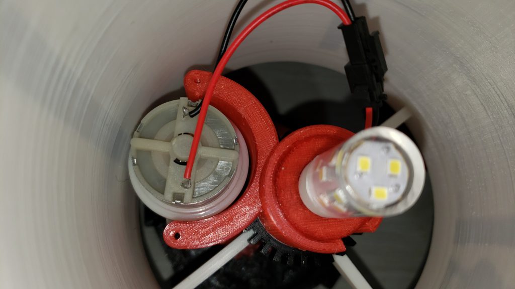
Starting with the motor assembly, you need the motor, the motor mount, the small gear, two #6 screws, a short M3 screw, and one half of a two pin connector pair.
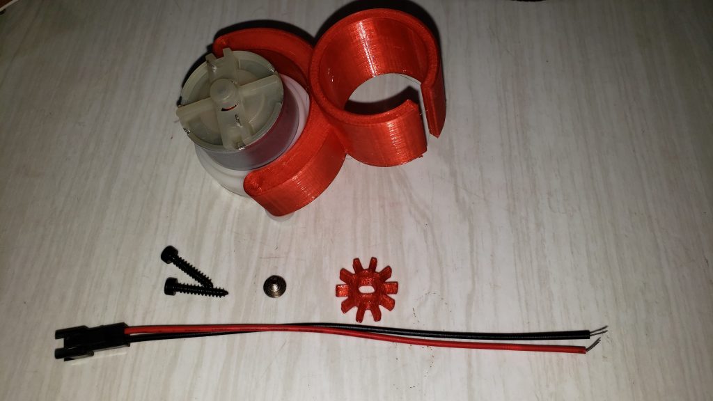
Cut the connector wires to approximately 3 inches and solder to the motor. The motor is bidirectional but this does establish rotation direction. If you have a preference in the direction of rotation, you may end up swapping the wires. Use the M3 screw to fasten the small gear to the motor and secure the motor to the motor mount. The gear is oriented toward the center of the motor mount. The final assembly should look like this.
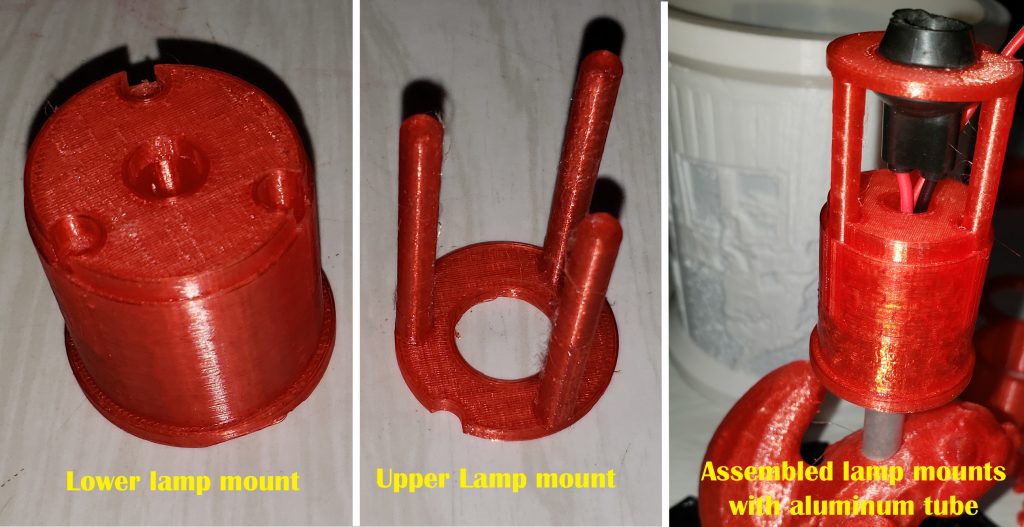
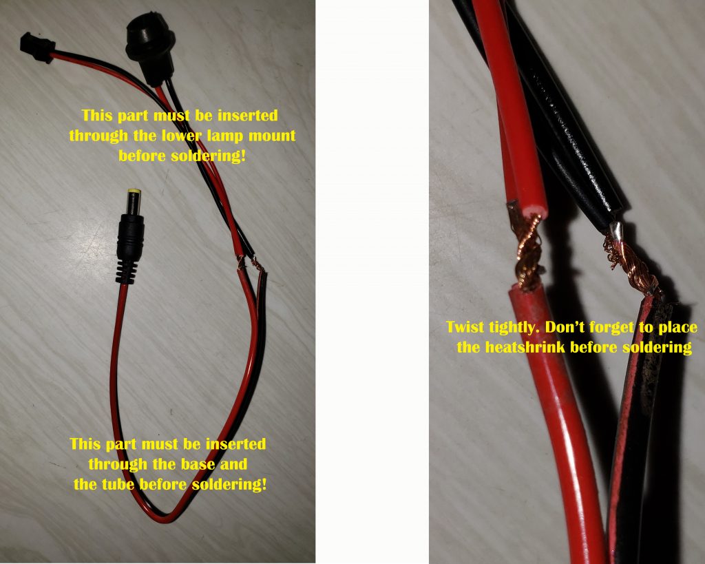
The wiring harness runs through the base, the aluminum tube and the lower lamp mount. Insert the tube into the base and slide the lower lamp mount onto the other end of the tube. This is a good time to decide how far above the base you want the lithopane. I cut my tube to about 6 inches. Cut the tube before continuing.
Now run the DC power wires through the base assembly (base, tube and lower lampholder), starting at the base. Take the lamp socket and the mating connector of the 2 pin connector you soldered to the motor. Although you can use tape, I used heat shrink to insulate the solder joints. If you do use heatshrink remember to put the heatshrink sleeves on the DC power cable, well away from where you will be soldering. Cut about an inch off the lamp socket wires. Strip the wires, connect all the reds together and all the blacks together. It will be a little bit easier if you wrap as shown but that’s up to you. Solder the joints but remember they will need to go back into the tube.
 Not that I don’t trust your work but now is good time to test the wiring. Connect the motor mount and verify that the motor operates. Don’t panic if the lamp doesn’t light. The lamp mount is bidirectional but the lamp only works for one orientation. Before deciding the lamp or wiring is defective, pull the lamp out, rotate it 180 degrees and plug it back in. If it’s still not working, you have some troubleshooting ahead of you. Assuming all is good, remove the lamp, position the heatshrink tubes and shrink it.
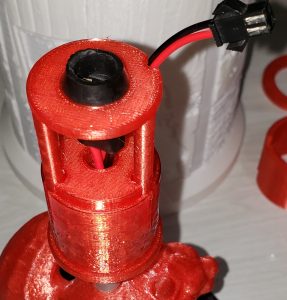
Push the lamp socket through the upper lamp holder and carefully assemble the upper lamp holder to the lower lamp holder while pulling the wires through the tube. The legs of the upper assembly should seat firmly into the lower assembly. I have to admit that I did not the angles just right on the base mount. It will work for any of the three possibilities but if you get the right orientation it fits like a glove. It should now look like this.
Push the large gear over the inside mounting collar of the lithopane. It should be a snug fit. With the 2 pin connector pointed up and routed into the grove in the upper lamp holder, attach the lithopane to the base assembly. At this point the lithopane should be able to rotate freely.
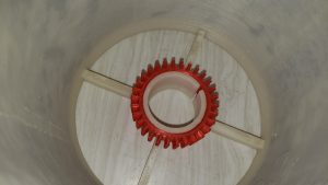
Lithopane with large gear
With the gear pointing down, push the motor assembly over the upper lamp mount. Be careful not to the catch the 2 pin connector. Use the notch or the slot in the motor collar. This is intended to be a tight fit and will take a small amount of dexterity. There’s a very slight lip on the lower lamp mount. Push the motor assembly all the way down until you feel resistance from this lip. At this point, the gears should be engaged and the lithopane will no longer rotate freely. Almost done.
Connect the motor assembly and plug in the lamp. Put the assembly on a level surface and apply power. As before, don’t panic if the lamp doesn’t illuminate. Just reverse it and plug it back in. Gently rotate the assembly so that the motor is located on the backside of your base.
Once you have everything working to your satisfaction, add the top cover and you’re done. Enjoy.
© 2019, Byron Seastrunk. All rights reserved.


Recent Comments