As with most engineering projects, it started with a need. In my case, as soon as I got high-speed Internet, I eagerly added several cameras. I chose Wyze because they are affordable, don’t require a monthly subscription, and offer excellent picture quality. Wanting to extend coverage beyond just my house, I opted to power the cameras with solar energy. Wyze uses a USB port for power, and conveniently, most of the solar controllers I use have a USB output. That marked the beginning of this intriguing project.
With both my chicken coop and the goldfish pond already powered by solar energy, I thought adding solar-powered cameras would be a walk in the park. It quickly became obvious my park existed in a very rough neighborhood because I was bombarded with issues almost immediately.
Using solar power in Texas, even though you design for round the clock operation, you have to accept that a string of cloudy days will eventually deplete your battery. This I knew and had accepted. What I hadn’t anticipated were two minor, yet disruptive, quirks of my system. As the sun begins to power up the battery, the USB ports activate. But, frustratingly, for a brief moment, the ports don’t provide a full 5V. This wouldn’t be an issue except that Wyze cameras can be finicky about starting up if the USB voltage isn’t a steady 5V. I found myself facing a 33% chance of the camera freezing in a nonfunctional state. The only solutions were to manually unplug it or to leave it to chance on the next cycle.
 No problem, I thought—a Zener diode and a small relay module should fix it, right? I even had a 3D-printed fixture, needing only a minor modification. Sadly I had underestimated the challenges. It turns out that activating a load just as the USB port reaches 5V causes a brief voltage dip, and the camera fails to receive a full 5V. Oops.
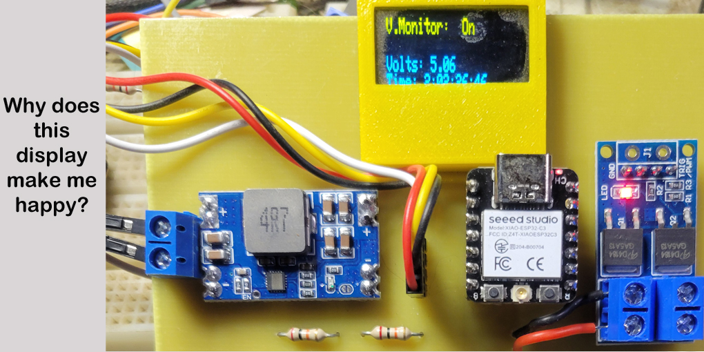
Adding a capacitor and timer for a delay was an option, but I was concerned about encountering more issues. A little musing and I found a possible solution that incorporated several opportunities to refine my skills further. Enter the SeeedStudio ESP32C3 microcontroller and a FET switch. This setup would monitor the voltage, activating the switch only after two solid minutes of adequate voltage and turning it off if it dropped below 5V. This would repeat indefinitely.
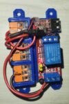
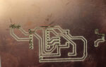
Handwired
After some coding and a bit of hand wiring, I had a prototype. It performed wonderfully—except when it didn’t. My overconfidence had led to a design with minimal troubleshooting tools. That’s when I had a stroke of genius: incorporate a miniature display from a previous project. This significantly eased the troubleshooting process. Better yet, it required adding only four wires to the existing setup.
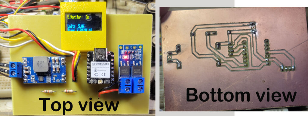
At last count, I had around eight cameras and only four with the handwired modules. It’s a simple design and I have a CNC. Why not create a PCB layout I could route with my CNC? Those were certainly skills I could apply to future projects.
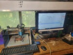
CNC Setup
Despite the simplicity of the design, creating component footprints with my chosen software, LibrePCB, proved more daunting than expected. I opted for a more rudimentary approach using inline connector pads to form the necessary patterns. Crude, yet effective. As for the CNC process, transitioning from the digital design in LibrePCB to physical boards via FlatCAM had its learning curve, punctuated by early setbacks like snapping my only 0.8 mm drill bit as the CNC spindle was driven into a support fixture. Totally my fault, having modified a parameter I did not completely understand.
Too deep
More obstacles in my path. I had not noticed before, but my CNC was almost ½ millimeter higher on the right side. It makes no difference when making wood nameplates but made a big difference in trying to etch a PCB. Fortunately, a few videos on YouTube helped me minimize the difference, and I finally had a PCB I could use.
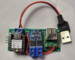
Assembly was surprisingly straightforward, marred only by a single manufacturing issue and no design flaws. I had successfully designed and fabricated a functional power control switch for my Wyze camera solar installations.
Conclusion:
Reflecting on the project, it required about three hours to hand wire each switch module. On the other hand I put in eight hours to become adept with LibrePCB, six more with FlatCAD, and an additional four hours fine-tuning the CNC process. Eighteen hours in total—the equivalent time it would take to manually wire six switches, coincidentally the number I needed.
Looking strictly at the numbers, one might argue that I should have stuck with hand wiring from the start. However, the journey taught me invaluable lessons in using schematic capture tools, operating FlatCAD, and producing custom PCBs on my CNC. On a slightly discouraging note, I discovered that once I had a PCB layout, I could have more boards than I’d ever need produced in China for less than $100. Of course, the initial layout has to be flawless. Otherwise, you will spend another $100 for each additional attempt.
Was it worth it? From a practical standpoint, perhaps not. But the journey brought immense satisfaction and a profound sense of achievement—watching my concept come to life was truly rewarding. I also gained a number of skills I can use in future projects. For me, this project was undeniably worth every moment.
Design Decisions and Lessons Learned:
– The prototype has a 12V to 5V converter because I have one solar controller that will not leave the USB ports active. Well, that and I originally thought there was a current limit issue with USB ports. The layout intentionally makes using the converter optional.
– The total area is significantly larger than the hand-wired version. I was going for proof of concept, not a final product. Not knowing the limitations of my CNC, I designed this as a single-sided board.
– I used ChatGPT to clean up my code for this project. The final code was much cleaner, but I spent an additional hour debugging the changes ChatGPT made to the software.
– The board is right on the limits of what I can produce on my Sainsmart ProVer 3018.
– I did try using my laser. Etching copper went well, but burning holes through the FR4 fiberglass was far less than optimal.
– I never got to the bottom of it, but I discovered if I had a voltage on pin A0 while trying to program the ESP32, attempts to program the device would fail.
A few credits:
– James Dean Youtube videos on CNCs and tramming: https://www.youtube.com/c/JamesDeanDesigns/videos
– CNC PCB Holder M6 by idleBit on Thingiverse: https://www.thingiverse.com/thing:2654304
– OLED SSD1306 .96″ display case (snap top) by scrugless on Thingiverse: https://www.thingiverse.com/thing:2985958
Design Package:
I did not write this to give you a full design package. I’m assuming very few of you have this specific need. However, I’ve attached a pdf for those of you that absolutely need to know. Please don’t disappoint me by trying to use the pdf layout as an exact template to recreate the board. Design Package
© 2024, Byron Seastrunk. All rights reserved.


Recent Comments